Adaptation
In this section we are going to show the adaptation process for TRON framework. We are going to use the smart lamp light controller example to highlight the supported features and to show how to use them.
Model Specification
TRON supports abstract requirement models in a sense that implementation under test (IUT) does not necessarily have to follow the structure of the model. User should use Uppaal to specify requirements by creating a timed automata model of the whole (closed) system, i.e. the model should contain requirements for the IUT and also the assumptions about its environment (user). The processes in Uppaal timed automata network communicate via channels. Every channel synchronization is an instantaneous event in the system, taking zero time as any other transition. So the simplest closed system suitable for testing using TRON consists of at least two communicating processes: IUT process and environment process. In this simple system the input event is fired whenever environment process shouts at some channel and IUT receives the channel synchronization, the output happens in the same manner but opposite direction.
The model of environment can be as simple as one process containing one location with a synchronized transition loop for each input/output channel synchronization. Such environment would test the most of IUT features/requirements as it is fully permissive, however this might be too expensive and unrealistic, especially if environment assumptions can be stated more precisely, e.g. modeling some case of system usage. It is important that environment is input enabled, i.e. it is able to consume any possible output produced by IUT, otherwise TRON will issue verdict "inconclusive" in case the received output event cannot be applied to environment.
In a more complex system the IUT (and environment) requirements may be modelled by many processes. In this case the system is partitioned into two sets of processes: the processes modelling the requirements for IUT (model of IUT) typically mimicking what the IUT should do and the processes for the environment assumptions (model of environment) mimicking what the tester should do. The IUT (environment) processes may communicate among themselves by channel synchronizations too, but such communication is treated as internal and not observable. The channel synchronization is treated as observable input/output event if and only if it is between the environment and IUT processes.
As noted before, the channel synchronization is an instantaneous event in timed automata network, hence the communication between the environment and the IUT is also treated as instantaneous. However real-time black-box testing is also a kind of remote testing, where the inputs/outputs are fed at one time instance and received slightly later as there is at least small communication delay. Even the slightest delay of electronic signal running short distance at a speed of light is significant as it might imply a different input and output event interleaving and hence a different outcome. The communication delay is especially significant on soft-real-time operating systems (such as Windows and Linux) where the process scheduling is a major contributor but is hardly predictable (Linux scheduler tries hard to be at most 10ms late and 2.6 branch usually fits into 1ms delay under low load conditions, see Latency Experiments). Currently TRON time-stamps the input and output events when they arrive/leave TRON process, hence the model of IUT should also include the processes of adapter proxying and slightly delaying the actual input and output to reflect such communication reality. The model of adapter also helps to make sure that the model of IUT is input enabled, i.e. IUT cannot refuse to accept the offered input, which might be important in testing features that are triggered only by that particular input (and time). TRON will not try to offer an input if the model of IUT is not able to consume it.
The model of the system should be validated in the Uppaal symbolic simulator to make sure the model reflects an intended system behavior and the verifier should be used to check at least that model does not contain deadlocks ("A[] not deadlock" must be satisfied). In extreme cases where system state space is too large and cannot be verified (e.g. adapter processes involve queueing of input/output events and hence blowup the state space), a more abstract version of the model should be verified. TRON might issue verdict "inconclusive" or "failed" if it runs into deadlock situation and/or give unreliable "last good state set" diagnostic information if deadlock is present but was avoided by taking other transitions.
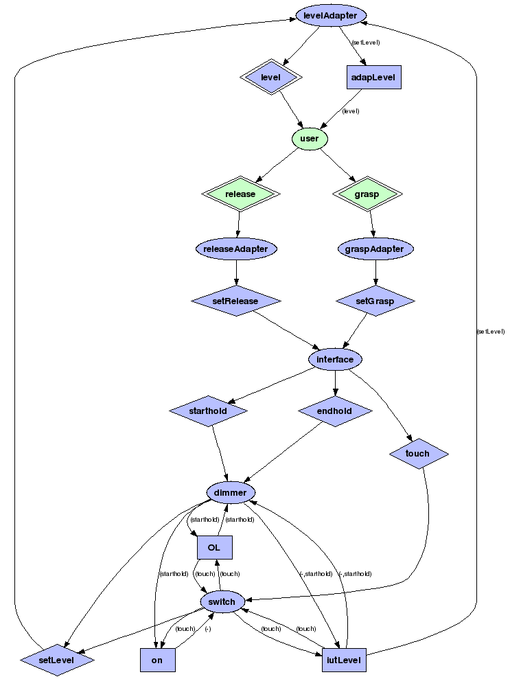
Example. Consider the smart lamp demo with the following model of the system: LightContr.xml (you are encouraged to load it into Uppaal). I will use the signal flow diagram LightContr.png to demonstrate how processes in this system communicate (see Test Interface Specification to produce signal flows of your own). The legend of this signal flow diagram is as follows: ellipse means process, rectangle means integer variable, diamond means channel, arrows indicate the flow of signal, i.e. process transmit on given channel if arrow is from ellipse to diamond, process receives on given channel if arrow is from diamond to ellipse, variable is being written by process if arrow points from ellipse to rectangle and variable is being read if arrow is from rectangle to ellipse. The labels on arrows indicate the channel synchronization when variable is accessed, dash means silent (internal) access without channel synchronization. TRON uses the observable input/output channel (double diamonds) declaration (see Test Interface Specification) to partition the system into the model of environment (light green items) and the model of IUT (light blue items). In this example, environment consists of user process communicating through input channels grasp and release and output channel level. The requirements for IUT are modeled by interface, dimmer and switch processes. The communication delay is modeled by levelAdapter, releaseAdapter and graspAdapter processes.
Test Interface Specification
Test interface is a set of observable input and output channels possibly with integer variables values bound to channel. Observable input and output channels define how the system model is partitioned into the model of IUT and the model of environment. The correct system partitioning is important in order to ensure correct verdict computation by using relativized timed input/output conformance relation (which means identifying and special treatment of IUT invariants which might interact with environment model as invariants are global in Uppaal semantics). The idea of correct partitioning is a complete and consistent separation of environment model and IUT model by inspecting the following control rules:
- Channels, that are not declared as inputs/outputs, are non-observable called internal.
- Internal channel belongs to environment (IUT) if it is used by environment (IUT) process (respectively). Model is inconsistent and cannot be partitioned if the internal channel is used by both environment and IUT.
- Process belongs to environment (IUT) if it uses the internal environment (IUT) channel (respectively).
- Variable belongs to environment (IUT) if it is accessed by environment (IUT) process without observable input/output channel synchronization. Variable is not cathegorized (can be either) if accessed consistently only during observable input/output channel synchronization.
- Process belongs to environment (IUT) if accesses environment (IUT) variable (respectively) without observable channel synchronization.
It might be tricky to get complete and consistent (all processes are assigned to either IUT or environment) partitioning. Currently the adapter API is the only way to specify the test interface. The easiest way to experiment with test interface and partitioning is by generating signal flow diagram of the system. The signal flow diagram in graphviz format can be obtained from TRON standard output with -i dot option on specific Uppaal model and entering the test interface information via standard input in the following tiny EBNF grammar (terminals are quoted in bold, this grammar is also used in TraceAdapter):
TIS ::= inputs outputs precision timeout
inputs ::= "input" channels ";"
outputs ::= "output" channels ";"
precision ::= "precision" integer ";"
timeout ::= "timeout" integer ";"
channels ::= | channel ( "," channel )* ";"
channel ::= channelname "(" variables ")"
variables ::= | variablename ( "," variablename )*
Here, the precision specifies the duration of one model time unit (mtu) in microseconds and timeout specifies how many model time units is allocated for testing. Upon success TRON will terminate with verdict "passed" when precision × timeout microseconds elapse and no fault is found.
Example. The following command lines produce signal flow in graphviz format which is further laid-out onto the PNG picture format by dot utility, the third line does it all in one:
tron -i dot LightContr.xml < LightContr.trn > LightContr.dot
dot -Tpng -o LightContr.png LightContr.dot
tron -i dot LightContr.xml < LightContr.trn | dot -Tpng -o LightContr.png
Note that TRON also adds a few constraints for the graph layout in dot file, in particular it specifies landscape A4 paper, which is handy for -Teps option but might not be good for some larger models.
If partitioning is not complete (some process, variable or channel is assigned to neither IUT nor environment) or inconsistent (according to rules some item is assigned to both IUT and environment) then TRON will write complains and warnings to the standard error stream. The verbosity of partitioning messages is controlled by -v option: -v 0 -- none, -v 1 -- errors, -v 2 -- warnings, -v 3 -- diagnostics. The diagnostic messages will show how TRON is trying to partition the processes, variables and channels by iteratively applying the control rules. It is also recommended to check the separation in the output stream from TRON once the test interface is specified during testing.
Currently (as of version 1.4 Beta 2) the variable usage in C-code functions is not analyzed, hence partitioning might work incorrectly. Also observable broadcast channels should be used with caution (IUT/environment cannot send and receive at the same time on observable broadcast channel). The source code for signal flow static analysis and partitioning will probably be available in the next release of UTAP library.
Observation Uncertainties
TRON is applying observable input and output events by the following algorithm: 1) time-stamp the event with the host machine clock, 2) convert to a model time representation in floating point number form 3) find the closest integers to the given floating point number 4) apply input/output event to the model state space as if it happened between the closest integers time points. Observation uncertainty is a tweak for such time-stamping scheme, which expands and shifts the time-stamping interval: the output event is expanded to the direction of past (as if it happened earlier than observed), the input event is expanded to the direction of future (as if it will happen later than it is actually sent). The observation uncertainty was an early idea to reduce state space explosion due to adapter models and still be able to handle the communication and scheduling latency.
The observation time uncertainty can be specified by -u option, see the output of tron -h. The parameters inpDelay and outDelay control how many microseconds the event time window is shifted and parameters inpRes and outRes specify how many microseconds the window is be expanded, which potentially might touch or cover a next time unit(s). Current implementation (1.4 Beta 2) does not treat the time-stamp shifts correctly as it is required to create a hole in a state space between possible outputs in the past and possible inputs, hence requires a more complicated state exploration algorithm. Values other than 0 for inpDelay and outDelay are not recommended. The values for inpRes and outRes should reflect the scheduling and communication latency, e.g. allow about 3000-4000 microseconds on Linux-2.6 (may vary on different machines).
Observation uncertainty is relevant only in testing in real world time and is irrelevant in virtual time.
Building Test Adapter
Normally, when TRON process is launched for testing the following happens:
- TRON parses and sets the command line options
- TRON looks for Uppaal timed automata model and loads it.
- TRON looks for adapter specified and attempts to create it via constructor call by passing a reporter object handle.
- Adapter constructor establishes connection to IUT (possibly launching another IUT process/thread, or simply connecting to remote IUT process).
- Adapter constructor configures the testing interface by declaring observable input/output channels, binding needed variables, sets the precision and the timeout for testing and returns the adapter handle to TRON.
- TRON statically analyzes the model and partitions the system into IUT and environment.
- TRON calls adapter.start() routine to indicate that no problems were found, adapter should finish any initializations and testing begins from the moment thread returns to TRON.
- Further input and output communication is asynchronous in a sense that IUT should use its own thread to report outputs to the reporter (which in turn will time-stamp and queue it) and TRON will call the method to register input (IUT is expected to add input to its input queue, notify its thread and return as soon as possible). Caution: adapter interface may deadlock if the same input-offering-thread (from TRON) is used by adapter to report the output from IUT. It is also important to release the lock on input queue (if any) in IUT adapter when reporting outputs to allow TRON to offer input while the output is being reported.
- After test is finished (via timeout or failure), TRON calls the adapter destructor to disconnect from IUT, cleanup and release all the resources.
Currently there are a few different adapter examples available as reference implementations, depending on platform and adapter method the actual action names may differ:
- Textual communication via standard I/O adapter (virtual time recommended). See source code using TraceAdapter in tracer directory under GNU environment (requires bash, GNU make, use Cygwin if on Windows). TraceAdapter uses the ANTLR lexer and parser to read the standard input stream (see how "make testsuite" example works for example traces accepted by TraceAdapter, it's even possible for human to interact with TRON).
- TCP/IP socket adapter for remote IUTs (both: virtual and real time). See Java source code of smart-lamp using SocketAdapter in java directory, java-doc. Remote adapter implementation in C/C++ can also be provided upon a request.
- Microsoft Visual C library adapter example (currently only real time). See source code of mouse button example in MSVC directory.
- GNU C library adapter example on Unix (both: virtual and real time). See source code of mouse button example in button directory.
Virtual Time
Much of real-time control software concerns mainly correct timing and functional behavior and time spent on computation is negligible or predictable. TRON's virtual time framework offers a possibility to test a real-time application in laboratory conditions where time flow is controlled, i.e. time is allowed to flow when all processes are explicitly waiting and is stopped when at least process is busy computing. Virtual time framework has an advantage that otherwise inherent latencies (OS scheduling, communication) are removed.
The idea is based on a concept of monitor, where mutex locking and unlocking wrap a negligible amount of atomic computations and temporary mutex release by waiting on conditional variable reflects the process' intent to delay and wait for a specific condition.
By default TRON assumes host machine's real time clock and virtual time clock can be turned on by option -Q log which also opens a server socket on port 6521 to serve any remote request for virtual clock. User can also change the port number to 1234 by using option -Q 1234 instead, just make sure that remote IUT will also use the same port number. Reference Java client implementation of remote virtual time clock can be found in java/tron/VirtualThread.java file.
POSIX C Example
POSIX (Portable Operating System Interface for uniX) way of creating a monitors is by using pthread_mutex_lock, pthread_mutex_unlock, pthread_cond_wait and pthread_cond_timedwait functions (see their manual pages e.g. on your Linux distribution). TRON binary (on Linux) exports the following substitute functions which call the OS's POSIX layer when testing in real time and uses virtual TRON's clock when testing in virtual time:
- tron_thread_create instead of pthread_create
- tron_mutex_init instead of pthread_mutex_init
- tron_mutex_destroy instead of pthread_mutex_destroy
- tron_mutex_lock instead of pthread_mutex_lock
- tron_mutex_unlock instead of pthread_mutex_unlock
- tron_cond_init instead of pthread_cond_init
- tron_cond_destroy instead of pthread_cond_destroy
- tron_cond_wait instead of pthread_cond_wait
- tron_cond_timedwait instead of pthread_cond_timedwait
- tron_cond_signal instead of pthread_cond_signal
- tron_cond_broadcast instead of pthread_cond_broadcast
- tron_gettime instead of gettimeofday
There are also functions to temporarily remove the current running thread from virtual time accounting and put it back to the pool of virtual time threads: tron_thread_deactivate and tron_thread_activate. These functions are not normally used, and exist only to simplify design of remote adapters like SocketAdapter.
Java Example
Example in java directory provides tron.VirtualLock class for controlling the state of (potentially remote) lock and creating tron.VirtualCondition variables. TRON's monitor paradigm is very similar to Java's synchronized methods, except that all participating threads should be created via tron.VirtualThread object, locking, unlocking, waits and notifications (signals) should be done explicitly on corresponding VirtualLock and VirtualCondition objects. See java-doc for more.