

In order to illustrate our approach we will in this section discuss a sample dynamic model, which we have developed with an early prototype of our envisioned dynamic exploration tool.
The problem domain of the example is geometric objects such as points, lines, and circles, on which a number of classical geometric constructions can take place. We imagine that we are about to construct a computer-based system, which support such a construction work. We start the design work by making a number of scenarios, which together constitute our dynamic model. First afterward, and based on this dynamic model, we deal with the static model of the involved classes. The problem, which we will consider here, is the construction of a circle through three given points.
As explained above, we represent a dynamic model as a tree. By
traversing this tree we get a trace of the messages in
the scenario. Figure 6 shows an example of such a
trace. The explanations of messages and object provisions are also
shown on the right-hand side of the figure, in italic font. The
example illustrates an object-oriented realization of the circle
construction through three given points. We see that the initial
scene consists of a single point, called A_POINT. A message
circle_on_points is sent to A_POINT with two newly provided points P1
and P2 as parameters. We next provide two lines L1 and L2 through the
three points. On each of L1 and L2 we now construct the central
lines .
The dynamic model includes a trace of the objects and messages which
are involved in the creation of the central line to L1. The central
line of L1 is constructed by drawing circles in the two extreme
points of the line segment. Notice how the start and ending points of
L1 are provided as part of L1. The two points, where these circles
intersect gives the direction of the central line. (The pattern is,
of course the same in the construction of the central line to L2, and
therefore this line segment is just provided ``magically''). Finally, the intersection
between the central line of L1 and the central line of L2 gives the
center of the resulting circle.
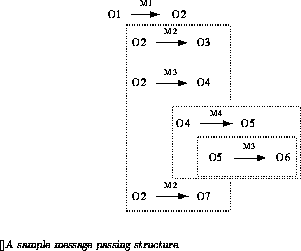
The actual data structures behind the trace is a tree implemented in
the Common Lisp Object System (CLOS) [1]. A sketch of such a tree is shown
in figure 7. The tree is akin to an abstract syntax tree. In the
current, early prototype, the tree is built via a simple custom made
structure editor. The structure editor works via a number of
specialized commands which augment, change and prune the tree structure.
Following each modification the trace is redrawn on outline form.
In the current prototype it is possible to analyze the trees in various ways. The most interesting analysis extracts the list of classes of the dynamic model together with a list of messages, which are activated on instances of the classes. The following is the result of such an analysis for the trace discussed above:
  ((CIRCLE
      LINE-THROUGH-INTERSECTION-POINTS)
   (LINE
      CENTRAL-LINE
      PARALLEL_WITH?
      INTERSECTION)
   (POINT
      CIRCLE-ON-POINTS
      DISTANCE))
Such a listing, based on a number of samples, may be seen as a starting point for the construction of the static model.


